- Home
- Suppliers
- Products
-
- Services
- Applications / references
- About us
- Contact
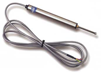
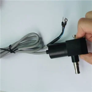
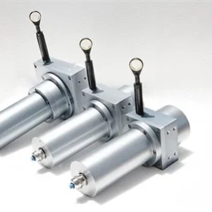
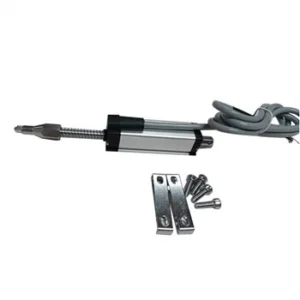
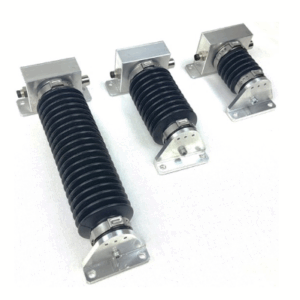
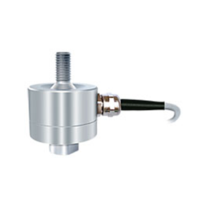
The MM displacement transducer uses strain gauge technology to provide a linearly proportional voltage output
in relation to movement. Its compact size and rugged construction make it ideal for a wide range of applications
such as geotechnical testing, R&D, aerospace, civil engineering, and automotive.
The strain gauge displacement transducer offers excellent accuracy — better than 0.1% on ranges of 0–25 mm
and 0.2% on the 0–50 mm and 0–100 mm versions — with infinite resolution and long-term stability.
The design incorporates a 4-arm active Wheatstone bridge with a nominal impedance of 350 Ω.
This design ensures excellent linearity, good temperature stability, and low current consumption,
making it ideal for battery-powered systems and equipment.
As a strain-gauge-based device, it is compatible with a wide range of standard analogue and digital instrumentation,
such as those used for load cells, pressure transducers, and torque sensors.
| Specification | Value |
|---|---|
| Stroke | 0–5 mm to 0–100 mm |
| Output | mV/V |
| Environmental Protection | IP54 |
| Accuracy | ±0.1% (0–5 mm to 0–25 mm) / ±0.2% (0–50 mm to 0–100 mm) |
| Warranty | 3 Years |
| Characteristics | LDS | Units |
|---|---|---|
| Stroke Length | 0–5 / 0–10 / 0–25 / 0–50 / 0–100 | mm |
| Rated Output | 5.0 / 5.4 / 7.3 / 8.8 / 7.5 | mV/V (nominal) |
| Non-Linearity | < ±0.10 | % of Rated Output |
| Repeatability | < ±0.10 | % of Rated Output |
| Operating Temperature Range | −10 to +60 | °C |
| Temperature Effect on Output | < 0.010 | % of Rated Output / °C |
| Temperature Effect on Zero | < 0.010 | % of Rated Output / °C |
| Safe Overload | See note 4 below | – |
| Excitation | 10 recommended (2–15 acceptable) | Volts AC or DC |
| Current Consumption | < 30 @ 10 V DC | mA |
| Input Resistance | 350 | Ohms (nominal) |
| Output Resistance | 350 | Ohms (nominal) |
| Insulation Resistance | > 200 | MΩ |
| Output Bandwidth | 100 | Hz (nominal) |
| Spring Force | 50–250 (100–400 on 100 mm) | gf (progressive) |
| Construction | Stainless Steel / Aluminium | – |
| Environmental Protection | IP54 | – |
| Cable | 2 m, 4-core screened, bend radius 10 mm | – |
| Weight (excluding cable) | 125 / 130 / 140 / 180 / 320 | grams |
Operational Notes:
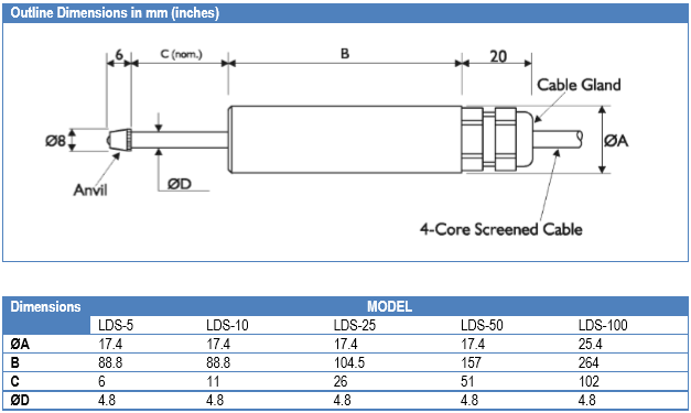
| Dimensions | LDS-5 | LDS-10 | LDS-25 | LDS-50 | LDS-100 |
|---|---|---|---|---|---|
| ØA | 17.4 | 17.4 | 17.4 | 17.4 | 25.4 |
| B | 88.8 | 88.8 | 104.5 | 157 | 264 |
| C | 6 | 11 | 26 | 51 | 102 |
| ØD | 4.8 | 4.8 | 4.8 | 4.8 | 4.8 |
| Wire | Designation |
|---|---|
| RED | +ve excitation |
| BLUE | −ve excitation |
| GREEN | +ve signal |
| YELLOW | −ve signal |
| SCREEN | GND – Not connected to body |
Copyright 2026 © All rights Reserved. Hemsida Webbdesign Interwebsite Webbyrå