| General |
| Integrated Sensors |
Triaxial accelerometer, triaxial gyroscope, and temperature sensors |
| Data Outputs |
Inertial Measurement Unit (IMU) outputs: acceleration, angular rate, Delta-theta, Delta-velocity |
| Inertial Measurement (IMU) Sensor Outputs |
|
Accelerometer / Gyroscope |
| Measurement Range |
Accelerometer: ±8 g (std) ±2 g ±4 g ±20 g ±40 g (opt)
Gyroscope: ±500 °/sec (std) ±250 °/sec ±1000 °/sec (opt) |
| Non-linearity |
Accelerometer ±0.04 % fs | Gyroscope ±0.06 % fs |
| Resolution |
Accelerometer 0.05 mg (+/-8 g) | Gyroscope <0.003 °/sec (500 dps) |
| Bias Instability |
Accelerometer ±0.08 mg | Gyroscope 8 °/hr |
| Initial Bias Error |
Accelerometer ±0.004 g | Gyroscope ±0.01 °/sec |
| Scale Factor Stability |
Accelerometer ±0.05 % | Gyroscope ±0.05 % |
| Noise Density |
Accelerometer 100 µg/√Hz (2 g) | Gyroscope 0.0075 °/sec/√Hz (500 °/sec) |
| Alignment Error |
Accelerometer ±0.05 ° | Gyroscope ±0.08 ° |
| Adjustable Bandwidth |
Accelerometer 225 Hz (max) | Gyroscope 500 Hz (max) |
| Offset Error over Temperature |
Accelerometer 0.02 % (typ) | Gyroscope 0.01 % (typ) |
| Gain Error over Temperature |
Accelerometer 0.05 % (typ) ±0.2 % (max) | Gyroscope 0.1 % (typ) ±0.4 % (max) |
| Sampling Rate |
1 kHz (accelerometer & gyroscope) |
| IMU Filtering |
First stage sigma-delta ADC sampled at 1 kHz; second stage user-adjustable digital low-pass filter. |
| IMU Data Output Rate |
1 Hz to 1000 Hz |
| Operating Parameters |
| Communication |
TTL serial (3.0 V dc, 9 600 bps to 921 600 bps, default 115 200) |
| Power Source |
+3.2 V to +5.2 V dc |
| Power Consumption |
360 mW (typ), 500 mW (max) |
| Operating Temperature |
−40 °C to +85 °C |
| Mechanical Shock Limit |
500 g / 1 ms absolute maximum survivability * |
| MTBF |
1 035 471 hours (Telcordia method gm/35C) |
| Physical Specifications |
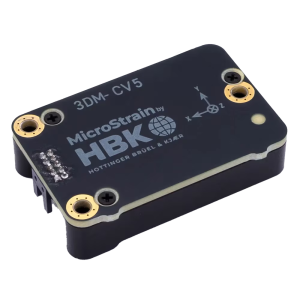
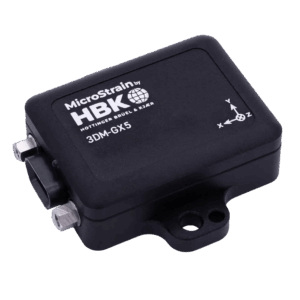
| Dimensions |
38 mm × 24 mm × 9.7 mm |
| Weight |
11 grams |
| Enclosure Material |
Aluminum |
| Regulatory Compliance |
CE, RoHS |
| Integration |
| Connectors |
Data/power output: Samtec FTSH Series. Connectivity board: Micro-D9 |
| Software |
SensorConnect and MIP Monitor software included; Windows XP/Vista/7/8/10 compatible |
| Data Communications Protocol (DCP) |
Protocol compatibility across GX3, GX4, RQ1, GQ4, GX5, CX5 and CV5 product families |
| Software Development Kit (SDK) |
MicroStrain Communication Library (MSCL) open-source license includes full documentation and sample code |
| Hardware Development Kit |
Option purchased separately |